Visitor:
![]()
![]()
When purchased, my '85 4Runner, it had stock springs that were badly rusted and sagging. In fact they had a nice reverse arch to them and the spring shackles were horizontal (pointing straight back)! The rear springs were riding on the overload leaf all the time, which probably contributed to the harshness of the ride.
The previous owner had installed a set of aftermarket Gabriel GasRyder shocks and the truck rolled on a set 4 nearly worn out (30x9.50) Bridgestone Desert Duelers. All in all, the ride was harsh and there was about 1" of clearance from spring to bump stop. All along I had intended to replace all that old rusty iron. I finally got around to it over the long July 4th weekend in 1997 when my company had a week-long shutdown.
![]()
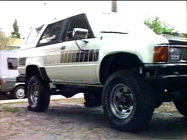 Here
is the view of my truck after the rear springs were swapped and before
the front was touched. Unfortunately, I finished the back end before I
thought of documenting the process. There's really not much to do in
back, just support the frame on jack stands, remove the tires, pull the
old springs off, and put the new ones on.
Here
is the view of my truck after the rear springs were swapped and before
the front was touched. Unfortunately, I finished the back end before I
thought of documenting the process. There's really not much to do in
back, just support the frame on jack stands, remove the tires, pull the
old springs off, and put the new ones on.
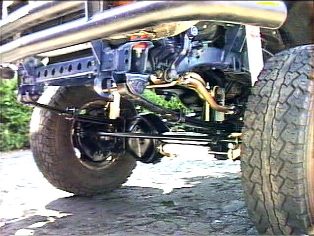
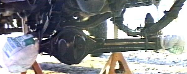
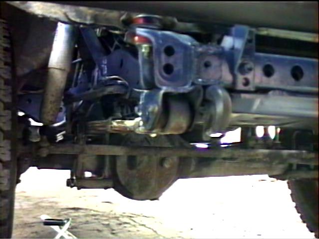 Check
out the reverse arch action on those front springs. I've already
sanded, primed, and painted the frame and added the ProThane polyurethane body mounts
at this point. You can see the rusty patina on the differential pumpkin.
Check
out the reverse arch action on those front springs. I've already
sanded, primed, and painted the frame and added the ProThane polyurethane body mounts
at this point. You can see the rusty patina on the differential pumpkin.
 Jack
it up, slide in some jack stands and yank the wheels. Now the fun
begins! I actually began a few weeks before by soaking all exposed
threads with WD-40 and I was able to get all nuts off intact and even
re-use them! I needed a bit of heat and persuasion to get the steering
damper off, though. A few of the spring shackle pins were badly rusted
to the rubber bushings. I found that screwing a nut back on the pin and
using a 2-1/2 lb. sledge hammer to persuade them to let go. On one, I
found that by rotating the shackle while applying WD-40 also helped. I
cleaned and sanded all the old pins and then coated them with NAPA
Spray-on silicone grease. It is a very sticky green aerosol grease. So
far no squeaks. The polyurethane spring and shackle bushings are
grooved and therefore hold a lot of grease. When I get the time, I'm
planning to replace all the pins with greaseable models.
Jack
it up, slide in some jack stands and yank the wheels. Now the fun
begins! I actually began a few weeks before by soaking all exposed
threads with WD-40 and I was able to get all nuts off intact and even
re-use them! I needed a bit of heat and persuasion to get the steering
damper off, though. A few of the spring shackle pins were badly rusted
to the rubber bushings. I found that screwing a nut back on the pin and
using a 2-1/2 lb. sledge hammer to persuade them to let go. On one, I
found that by rotating the shackle while applying WD-40 also helped. I
cleaned and sanded all the old pins and then coated them with NAPA
Spray-on silicone grease. It is a very sticky green aerosol grease. So
far no squeaks. The polyurethane spring and shackle bushings are
grooved and therefore hold a lot of grease. When I get the time, I'm
planning to replace all the pins with greaseable models.
 Now's
a good time to nuke that rust. All parts were cleaned of accumulated
grease, rust sanded down to bare metal, primed with zinc-rich
galvanizing primer and painted with a black epoxy paint.
Now's
a good time to nuke that rust. All parts were cleaned of accumulated
grease, rust sanded down to bare metal, primed with zinc-rich
galvanizing primer and painted with a black epoxy paint.
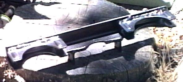
![]() Out
with the old springs, in with the new! The greaseable spring pads (in
between the leaves) are very cool.
Out
with the old springs, in with the new! The greaseable spring pads (in
between the leaves) are very cool.
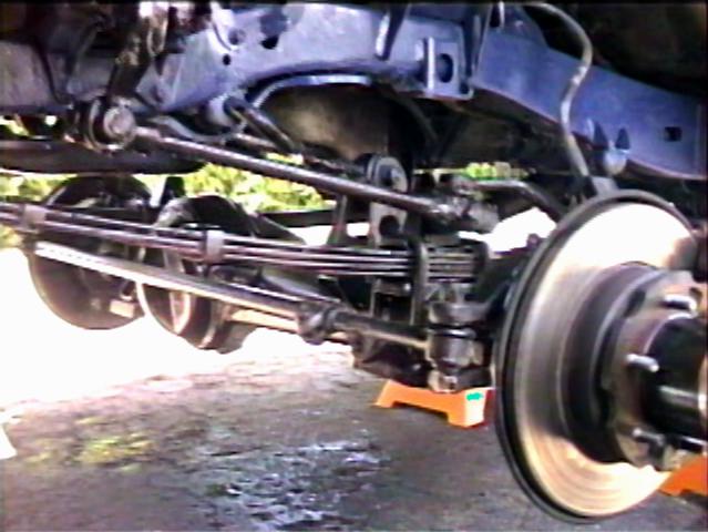
 Got
the new springs on there, but that brake hose and drag link look to be
stretched to their limit.
Got
the new springs on there, but that brake hose and drag link look to be
stretched to their limit.
 A
new stainless steel brake hose does the trick. I also took this
opportunity to completely flush the old brake fluid out. I used a
one-man vacuum brake bleed setup and bled the front and rear lines
after replacing the hoses. It took about 1 qt. of new brake fluid to
flush out the old stuff. Don't forget forget to bleed the rear brake
proportioning valve, too. While I was at it, flushed/bled the clutch
hydraulics, too.
A
new stainless steel brake hose does the trick. I also took this
opportunity to completely flush the old brake fluid out. I used a
one-man vacuum brake bleed setup and bled the front and rear lines
after replacing the hoses. It took about 1 qt. of new brake fluid to
flush out the old stuff. Don't forget forget to bleed the rear brake
proportioning valve, too. While I was at it, flushed/bled the clutch
hydraulics, too.
I noticed that the front brake pads were badly worn so replaced them a little later. I originally used an extended front torque rod bracket with the stock torque rod. It went on fine, but then later I noticed it was under compression when the vehicle was level. This was pre-loading the springs, twisting the axle back, increasing the wheel caster. I removed the stock rod and add-on bracket and replaced them with a Ranch adjustable torque rod. It has a threaded Heim joint on on end (urethane bushing on the other). You adjust the length so there is no pre-load at rest. It really improved the steering with less caster, its much more stable now.
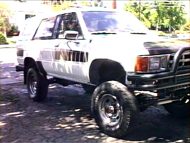
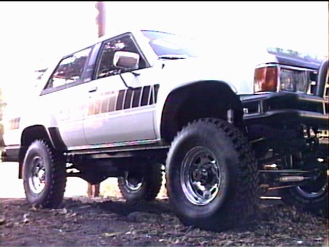
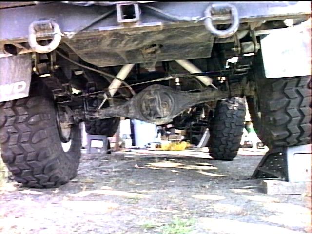
 And
the finished project. Note the new SuperLift dropped drag link, the
dual steering stabilizers and torque rod bracket. This picture taken
with the old 30x9.50 tires. The adjustable drag link is nice in that it
allows for centering the steering wheel. For centering, just measure
the distance the steering sector arm moves between wheels straight and
steering wheel centered. The arm ends are 16 TPI, you can do the math.
I have found it a little tricky to adjust/tighten properly, the rear
seat seems to hang up before compressing the internal spring, resulting
in loose steering. Plan on a few adjust/tighten/check cycles.
And
the finished project. Note the new SuperLift dropped drag link, the
dual steering stabilizers and torque rod bracket. This picture taken
with the old 30x9.50 tires. The adjustable drag link is nice in that it
allows for centering the steering wheel. For centering, just measure
the distance the steering sector arm moves between wheels straight and
steering wheel centered. The arm ends are 16 TPI, you can do the math.
I have found it a little tricky to adjust/tighten properly, the rear
seat seems to hang up before compressing the internal spring, resulting
in loose steering. Plan on a few adjust/tighten/check cycles.
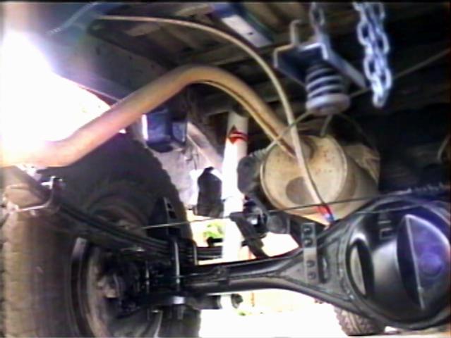 Unfortunately
I didn't get any in-progress shots of the rear end work. Here is a shot
of the left rear corner.
Unfortunately
I didn't get any in-progress shots of the rear end work. Here is a shot
of the left rear corner.
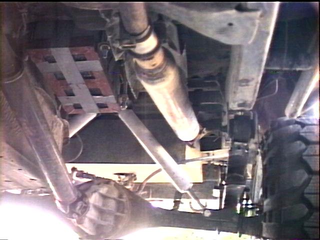
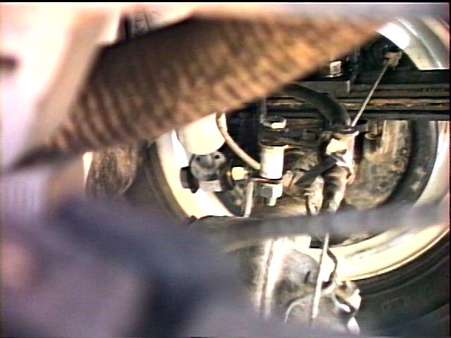
 Here's
a closeup shot showing the extended bracket for the brake proportioner
and the new differential breather hose attachment. The extension
bracket supplied with the NWOR spring set only has a 2-1/2" offset
between the old and new holes (I assume for a 2-1/2" lift). I
noticed that the brake bias was still heavy on the front, (after
stop-n-go driving, the front rims are hot, the rear are cool). Since
the function of the valve is to sense a lightly loaded rear-end (i.e.
the springs are high) and reduce rear braking, my extra 1-1/2" of
lift simulates a light load. My final solution is pictured below.
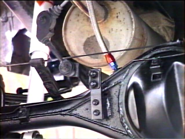
Here's
a closeup shot showing the extended bracket for the brake proportioner
and the new differential breather hose attachment. The extension
bracket supplied with the NWOR spring set only has a 2-1/2" offset
between the old and new holes (I assume for a 2-1/2" lift). I
noticed that the brake bias was still heavy on the front, (after
stop-n-go driving, the front rims are hot, the rear are cool). Since
the function of the valve is to sense a lightly loaded rear-end (i.e.
the springs are high) and reduce rear braking, my extra 1-1/2" of
lift simulates a light load. My final solution is pictured below.
For the vent, I simply removed the stock breather fitting and then ran a 1/8" NPT tap (greased) into the hole in the differential. Then I could use standard 1/8" pipe thread fittings. In back, I ran a straight fitting out of the axle, in front, I used a close nipple and a 45° elbow to point the vent towards the firewall. I installed separate vent lines and filters with short, uphill tubing runs to filters for each line. The front filter is high on the firewall, the rear vent on the tire carrier frame. Both are approx. 4' off the ground.
 And
the after shot. Still has the old 30x9.50 Bridgestone rubber on at this
point.
And
the after shot. Still has the old 30x9.50 Bridgestone rubber on at this
point.
 And
here it is w/ BFG 33x9.50 MTs, ready to rock and roll !!!
And
here it is w/ BFG 33x9.50 MTs, ready to rock and roll !!!
After a year of bolting on bumpers, fuel tanks, and other bits, I found I needed to fine tune the suspension.
So I pulled the lift spring packs apart as well as the old stock spring packs. I cleaned everything up and began to play. In back, I took the main leaf from the lift pack (higher arch = more droop) and all the rest of the stock leaves and that is my new rear spring. It sits flat, just resting on the heavy overload leaf, but droops as far as the full lift pack did. I added 1.5" longer spring shackles and a 3 degree shim. The softer spring got me 1.5" more compression and the longer shackle added 1.5" more droop. However, the soft KYB shocks allowed the rear end to bottom out and they were too short for the added droop, so I swapped in a pair of RS-5143 shocks. They are a bit too long, so I added some 1.5" blocks to my cut-down bumpstops to protect the shocks.
In front, I used the first two lift leaves and added the lower stock leaves (1 on the driver's side, 2 on the passenger side) to level the front. I added 1.25" longer spring shackles to keep the springs off the frame. As a side benefit, my 33" tires no longer rub the wheel well under compression! A set of RS-5115 shocks up front handle the extra droop of the longer shackles.
All in all, I've lowered the truck 2 full inches from the original lift height. The front wheel wells were about 36" high stock (w/ 30" tires) and after the springs/tires/body lift was done, it measured 43" (7" total lift). Now it sits at 41", subtracting the 1" body lift and 1.5" larger tire height, I guess I have 2.5" lift springs now. And considering the longer shackles, its probably closer to 2".
Well, after a year on Phase II, I found that I had pushed the stock suspension to its limits. In front, the shocks were limiting droop and with the repeated strain, one lower shock mount tore off the axle. In back, the shocks limited compression. Also, I was not really happy with the relocated holes in the front spring perches. So, I put the rear springs back to the original NWOR setup (for now) and then acquired a rear spring pack from an '83 short bed pickup (thanks to Barney McNamara for that). The pickup springs had about 3" extra free arch than my 4Runner springs, so I made use of the three main p/u leaves, then the 3rd and 4th leaves from my stock 4Runner pack then the 4th leaf from the p/u pack. After measuring, I found that using symetrical springs in front resulted in a fairly level body. No need to fool with the left and right spring nonsense.
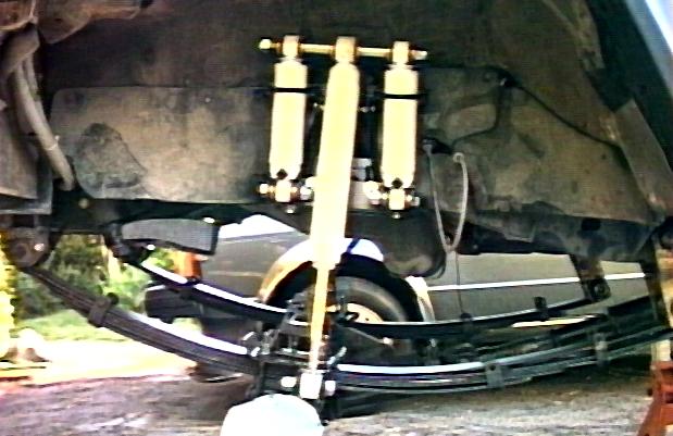 A
custom, long-travel triple shock (based upon a
concept by James Stevenson) up front eliminates the shocks from
limiting travel and allows for re-centering the shock on the axle that
now lives 2" ahead of it's stock location. I re-used my rear 5143
shocks in front, since they have more than enough travel when mounted
to the pair of 9120s. This nets me about 15" of front shock
travel, which should last me for a while :-) In preliminary testing, I
can just get the auxiliary shocks to lift a bit at full compression and
I still have about 2" of excess down travel. The whole idea was to
eliminate any shock limits of both up and down travel and I think I
succeeded.
A
custom, long-travel triple shock (based upon a
concept by James Stevenson) up front eliminates the shocks from
limiting travel and allows for re-centering the shock on the axle that
now lives 2" ahead of it's stock location. I re-used my rear 5143
shocks in front, since they have more than enough travel when mounted
to the pair of 9120s. This nets me about 15" of front shock
travel, which should last me for a while :-) In preliminary testing, I
can just get the auxiliary shocks to lift a bit at full compression and
I still have about 2" of excess down travel. The whole idea was to
eliminate any shock limits of both up and down travel and I think I
succeeded.
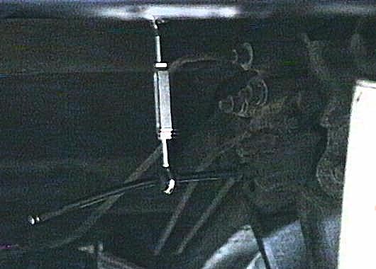
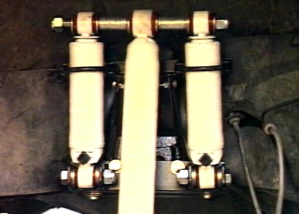 Here's
a closeup of the upper mount. The basic idea with this design is that
the upper shock mount moves up and down.
Here's
a closeup of the upper mount. The basic idea with this design is that
the upper shock mount moves up and down.
 Here's
a closeup of the lower mount, which I welded to the flipped u-bolt
plate. This allowed me to position it 2" behind the axle center.
If I had not moved the axle forward, I could have use the stock shock
mounting bracket.
Here's
a closeup of the lower mount, which I welded to the flipped u-bolt
plate. This allowed me to position it 2" behind the axle center.
If I had not moved the axle forward, I could have use the stock shock
mounting bracket.
 Since
I was no longer using the stock shock mounts (or sway bar or torque
rod), I decided to cut off all that excess steel while I had the axle
torn down. The passenger shock mount had already torn itself off.
Cutting wheels and a air hammer with cutting chisel took off the bulk
of the bracketry and an electric grinder smoothed off the remainder.
Since
I was no longer using the stock shock mounts (or sway bar or torque
rod), I decided to cut off all that excess steel while I had the axle
torn down. The passenger shock mount had already torn itself off.
Cutting wheels and a air hammer with cutting chisel took off the bulk
of the bracketry and an electric grinder smoothed off the remainder.
 Here's
a look at my bolt-on lower shock mount. I serves a few functions beyond
the attachment point for the auxiliary shocks. Firstly, it widens the
bump stop pad on the frame to give a bigger target for the bump stop to
hit, since my axle is relocated. Also, the 7/16" bolts that attach
it to the frame made for handy frame ground studs for my dual battery
setup.
Here's
a look at my bolt-on lower shock mount. I serves a few functions beyond
the attachment point for the auxiliary shocks. Firstly, it widens the
bump stop pad on the frame to give a bigger target for the bump stop to
hit, since my axle is relocated. Also, the 7/16" bolts that attach
it to the frame made for handy frame ground studs for my dual battery
setup.
 Here's
a closeup of the auxiliary shock saddle clamp. I found a 2-1/4"
muffler clamp was a perfect fit for the Rancho shock tubes. The two
clamps are welded to a piece of 1x1-1/8" angle and two tabs below
allow the assembly to be bolted to the cut off stock shock tower. I
used some rubber sheeting to isolate the shock tube from the metal of
the clamp. The purpose of this component is to keep the auxiliary
shocks from "flopping" around and also to "aim"
them out enough to allow full up-travel under the fender.
Here's
a closeup of the auxiliary shock saddle clamp. I found a 2-1/4"
muffler clamp was a perfect fit for the Rancho shock tubes. The two
clamps are welded to a piece of 1x1-1/8" angle and two tabs below
allow the assembly to be bolted to the cut off stock shock tower. I
used some rubber sheeting to isolate the shock tube from the metal of
the clamp. The purpose of this component is to keep the auxiliary
shocks from "flopping" around and also to "aim"
them out enough to allow full up-travel under the fender.
 Here's
the finished product in full compression. Gotta love that clearance at
the rear fender, now have room for 35's no problem. I did have to
install longer s/s brakelines and get my driveshaft slip yoke modified
for extra travel and I also had to fabricate some 2" longer spring
shackles to handle the extra length. The entire project was done as a
bolt-on, only had to cut the top of the factory shock mount.
Here's
the finished product in full compression. Gotta love that clearance at
the rear fender, now have room for 35's no problem. I did have to
install longer s/s brakelines and get my driveshaft slip yoke modified
for extra travel and I also had to fabricate some 2" longer spring
shackles to handle the extra length. The entire project was done as a
bolt-on, only had to cut the top of the factory shock mount.
 In
back, custom shock mounts allow long travel 9012 Ranchos to fit without
limiting up or down travel. A u-bolt flip and custom lower shock mounts
eliminate welding the mounts to the axle. Above, a shock mount on the
round crossmember allows room for the longer body shocks plus angles
them over for increased travel. The mount is a 14" length of
2.5x2.5x1/4" angle with a piece of 2x1/4" flat bar welded (to
form a "U") that wraps around the round crossmember. A pair
of 5/8" bolts welded to the angle function as shock pins and a
pair of 7/16" bolts go through the angle and round tube to hold it
all in place. I sized and shimmed the bolts so that the nut just
bottoms out on the threaded portion of the bolt, so as not to crush the
round crossmember. You'll also note my muffler had to be moved over a
few inches to clear the shock and the red box is my dual battery tray.
In
back, custom shock mounts allow long travel 9012 Ranchos to fit without
limiting up or down travel. A u-bolt flip and custom lower shock mounts
eliminate welding the mounts to the axle. Above, a shock mount on the
round crossmember allows room for the longer body shocks plus angles
them over for increased travel. The mount is a 14" length of
2.5x2.5x1/4" angle with a piece of 2x1/4" flat bar welded (to
form a "U") that wraps around the round crossmember. A pair
of 5/8" bolts welded to the angle function as shock pins and a
pair of 7/16" bolts go through the angle and round tube to hold it
all in place. I sized and shimmed the bolts so that the nut just
bottoms out on the threaded portion of the bolt, so as not to crush the
round crossmember. You'll also note my muffler had to be moved over a
few inches to clear the shock and the red box is my dual battery tray.
 Here,
you can just see the lower shock mount. I fabricated the lower mount
out of a piece of 3/8x2" flat bar and welded some 3/16x1.5"
flat bar underneath for the double shear shock mount. The 3/8" bar
is drilled for the spring center bolt and sits on the bottom of the
spring pack. I may ultimately weld this bar to the spring perch.
Here,
you can just see the lower shock mount. I fabricated the lower mount
out of a piece of 3/8x2" flat bar and welded some 3/16x1.5"
flat bar underneath for the double shear shock mount. The 3/8" bar
is drilled for the spring center bolt and sits on the bottom of the
spring pack. I may ultimately weld this bar to the spring perch.
Also visible is the 1" spacer I installed on the e-brake cable attachment point to allow more down travel. It's just a 1" piece of 3/4" aluminum tubing and a longer bolt.
 Here's
a shot from the rear showing the crossed over shocks. Ultimately, I'll
be installing some trick 56" Alcan springs to replace the stock
47" long ones to really make full use of the shock travel I now
have, which should be about 17" vertical and the shock mount. One
reason I didn't want a weld on attachment was that if needed, I wanted
to be able to convert this to something along the lines of James Stevenson's
long travel dual shock concept.
Here's
a shot from the rear showing the crossed over shocks. Ultimately, I'll
be installing some trick 56" Alcan springs to replace the stock
47" long ones to really make full use of the shock travel I now
have, which should be about 17" vertical and the shock mount. One
reason I didn't want a weld on attachment was that if needed, I wanted
to be able to convert this to something along the lines of James Stevenson's
long travel dual shock concept.
![]()
While I had the springs off the truck, I decided to measure the spring rates. By turning the springs upside down and measuring the distance from the ground to the top of the spring (unloaded). Then, I stood on the spring and measured the deflection. Using this admittedly crude technique yielded the following rates:
Conducting the same experiments on the various leaves led me to the conclusion that the bulk of the stiffness in the spring pack comes from the lower, shorted leaves. In fact, by swapping the stock lower leaves onto the higher arched, main lift leaves netted me a spring with the same 260 lb/in spring rate as stock with the added droop of the lift pack.
Below, I've summarized the specifications of the various spring leaves from the stock and NWOR 3.5" spring packs. The forward and rear dimensions represent the length of the spring in front of and behind the center bolt hole.
|
|
||||||||||||||||||||||||||||||||||||||||||||
|
|
Notes:
Here's some dimensions for the Gas-A-Just shocks that came with my 3.5" spring kit. THe KYBs are a good shock on the road and for mild off-roading, like washboard gravel and dirt. I found that coupled with a stiff spring they are OK in heavier off-roading, but when I went to a softer spring, I started bottoming out more. Also, with the increased travel of the softer spring packs, I found the shocks were limiting my suspension droop because they were not long enough. Anyway, if you are looking for a decent 3-4" lift shocks, I can make you a good deal on a set of slightly used KYBs.
Front:
Rear:
I assembled and reformatted this Rancho shock selection table to make it easier to find shocks matching a given length requirement.
![]()
Disclaimer: This modification changes your vehicles braking system. This is what I have done and while it works for me, if you choose to follow these directions, do so at your own risk.
Most Toyota mini-trucks have front disk brakes and rear drum brakes. Drum brakes are "self-energizing" meaning that they are designed such that the brake shoes are forced into tighter contact with the drum under load. If you remember your bicycle with caliper brakes, notice how the front brake was stronger than the back one? This is because the front caliper is mounted in front of the fork and the arms are pulled forward under braking, forcing the brake pads to ride up the bevel on the rim, gripping that much tighter.
Disk brakes, on the other hand, move directly towards the brake disk, and are very linear in their braking force. So, on a vehicle with front disk and rear drum brakes, some sort of front/rear brake biasing is needed (less pressure to the rear, more to the front).
On a pickup, the weight on the rear axle can very greatly depending on what's in the bed. So, Toyota added a load sensing brake proportioning valve that tries to sense the load on the rear axle and vary the brake bias accordingly. At light loads, the bias is towards the front, to keep the rear wheels from locking. At heavy loads, the bias is moved towards the rear, to spread the braking force more evenly. This sensing is done via a rod attached between the axle and the valve (that is installed on the inside of the frame). As the axle is loaded, the frame and axle get closer together as the springs compress, making the lever move.
One problem encountered when adding suspension lift to the rear axle, is that the valve senses this as a lightly loaded condition, and effectively cuts out the rear brakes. So, to compensate for this, an extension bracket needs to be installed to lift the point of attachment for the arm to compensate for the amount of lift. If you add 2" of lift, you should have a 2" extension bracket. This will move the arm back into the useable range of the proportioning valve.
On my 4Runner, I did add a bracket initially, but after trying two different lengths, neither of which worked perfectly, I opted for a different approach. Since the 4Runner is like a partly loaded pickup (rear shell and rollbar) the rear axle loading is not subject to the variations of an actual pickup.
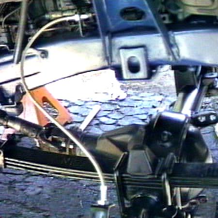
 I
removed the original extension bracket and my longer one, too, and cut
the rod to the proportioning valve and tied it to the body with an
adjustable turnbuckle. This is adjusted to keep the arm about
1/4-1/2" below the full up position. This setting seems to give a
balanced front/rear brake bias. It also looks much cleaner back there
with all that hardware gone. On the valve arm, the turnbuckle eye is
sandwiched between two O-rings that fit tightly to keep it in place.
The upper eye is attached to a metric-threaded screw-eye that fits
nicely into a pre-threaded hole* in the bed.
I
removed the original extension bracket and my longer one, too, and cut
the rod to the proportioning valve and tied it to the body with an
adjustable turnbuckle. This is adjusted to keep the arm about
1/4-1/2" below the full up position. This setting seems to give a
balanced front/rear brake bias. It also looks much cleaner back there
with all that hardware gone. On the valve arm, the turnbuckle eye is
sandwiched between two O-rings that fit tightly to keep it in place.
The upper eye is attached to a metric-threaded screw-eye that fits
nicely into a pre-threaded hole* in the bed.
* I'm truly amazed at the number of threaded holes Toyota saw fit to put in the 4Runner. I bet they could save 100 lbs. by removing all those welded in nuts and threaded inserts. But on the other hand, I've found many times that a conveniently located existing hole is right where I need it.
![]()
In other words, how does it work?
Well, I have had the truck off-road a few times since installing the new suspension and I am very impressed with the performance. Here's a few pictures show you the capabilities from Hollister Hills.
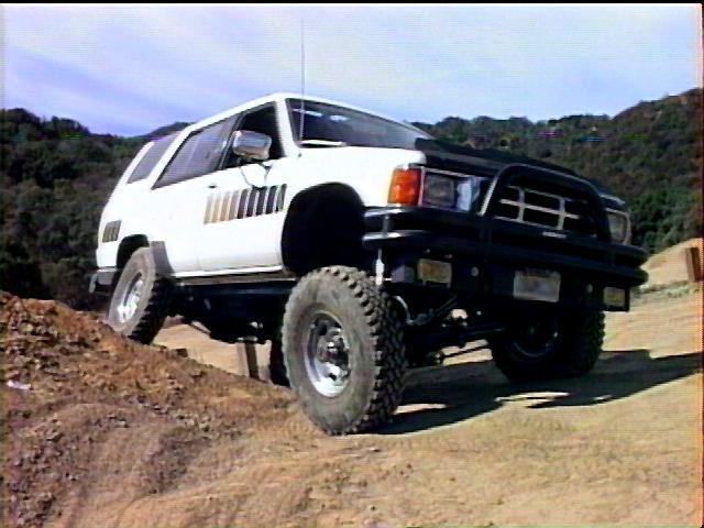 The
front bump stop is less than an inch from touching here. Also, check
out my custom front valence. I've got the fog lights recessed behind
wire mesh grills. It comes off in less than a minute with 2 1/2"
grade 8 bolts and a single connector for the fog lights. It's now for
sale since I installed my new
winch bumper.
The
front bump stop is less than an inch from touching here. Also, check
out my custom front valence. I've got the fog lights recessed behind
wire mesh grills. It comes off in less than a minute with 2 1/2"
grade 8 bolts and a single connector for the fog lights. It's now for
sale since I installed my new
winch bumper.
 I
guess these stock rate NWOR springs are not as stiff as people say. It
looks like they compress up nicely. Actually reminds me of the old springs in this shot.
I
guess these stock rate NWOR springs are not as stiff as people say. It
looks like they compress up nicely. Actually reminds me of the old springs in this shot.
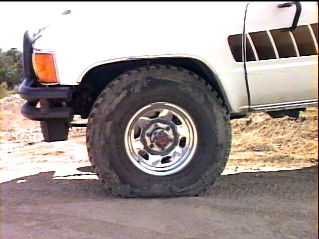 When
the front shackle swings back (touching the frame here), the front tire
moves up and back. There is the slightest of rubbing occurring at the
lower corner of the wheel well here. I've since trimmed a bit of the
seam away from the inner well, flattened the rest of it out and tucked
the wheel well liner behind the lower lip of the fender. An inch of
body lift and 1.25" longer shackles seem to have completely
eliminated the rubbing (with the 33x9.50 tires - my 33x15.50 Swampers
still rub while turning - to solve this requires moving the axle
forward). I was running 14 PSI front and rear here, under full load the
tire flattens out nicely.
When
the front shackle swings back (touching the frame here), the front tire
moves up and back. There is the slightest of rubbing occurring at the
lower corner of the wheel well here. I've since trimmed a bit of the
seam away from the inner well, flattened the rest of it out and tucked
the wheel well liner behind the lower lip of the fender. An inch of
body lift and 1.25" longer shackles seem to have completely
eliminated the rubbing (with the 33x9.50 tires - my 33x15.50 Swampers
still rub while turning - to solve this requires moving the axle
forward). I was running 14 PSI front and rear here, under full load the
tire flattens out nicely.
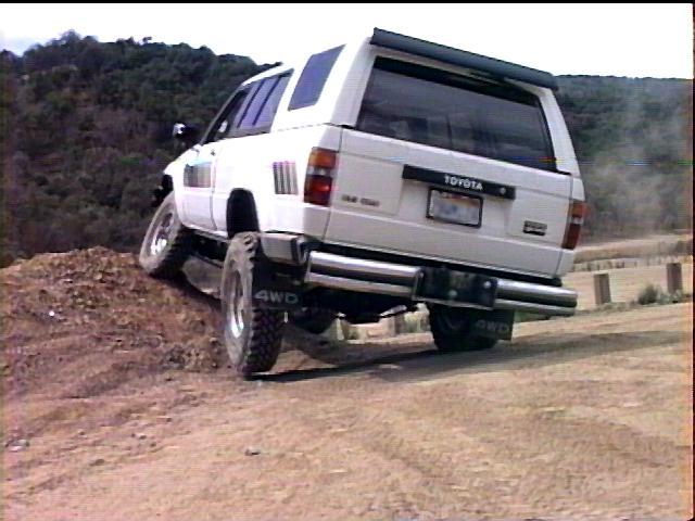 You'll
notice the left rear is just off the ground, and below, you'll see the
reason why.
You'll
notice the left rear is just off the ground, and below, you'll see the
reason why.
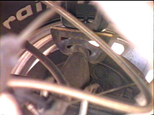 I'm
sure I installed the rear bump stops wrong! I installed the 2.5"
poly stops over the axle and left the stock rubber ones in place, since
they were attached to the upper u-bolt plate. I've since cut off the
bump stock extension from the frame and attached the poly stop directly
to the frame. I still use the stock bump stops and currently have
1.5" of blocking to limit the compression for the shocks and rear
drive line.
I'm
sure I installed the rear bump stops wrong! I installed the 2.5"
poly stops over the axle and left the stock rubber ones in place, since
they were attached to the upper u-bolt plate. I've since cut off the
bump stock extension from the frame and attached the poly stop directly
to the frame. I still use the stock bump stops and currently have
1.5" of blocking to limit the compression for the shocks and rear
drive line.
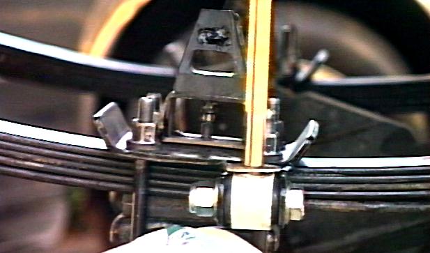
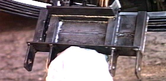
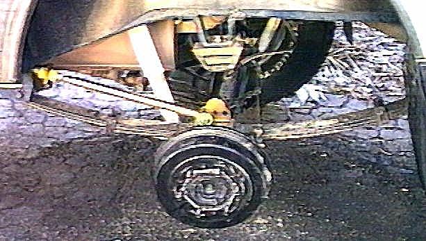 The higher arched rear springs were causing some rear axle wrap under
acceleration. The rear locker probably doesn't help matters, either.
Anyway, I debated on what to do about this and decided to try a rigid
traction bar. It consists of three main parts, a bracket that replaces
the stock bump stop plate under the u-bolts, a bracket that attaches to
the spring hanger, and a threaded steel bar with poly urethane bushings
on both ends. Installation was easy on the driver's side. The passenger
side is quite tight with the gas tank in the way, and I had to bend the
lip of the tank up a bit to get room for the installation. The rear
bracket is taller than the stock bump stop, leaving only a few inches
of travel, so I ended up cutting the upper bump stop extension from the
frame. This took about 1 hour per side with an air saw. Then I drilled
and tapped a hole in the frame to accept the mounting stud on the
polyurethane bump stop. Now, I've got loads of room for suspension
travel.
The higher arched rear springs were causing some rear axle wrap under
acceleration. The rear locker probably doesn't help matters, either.
Anyway, I debated on what to do about this and decided to try a rigid
traction bar. It consists of three main parts, a bracket that replaces
the stock bump stop plate under the u-bolts, a bracket that attaches to
the spring hanger, and a threaded steel bar with poly urethane bushings
on both ends. Installation was easy on the driver's side. The passenger
side is quite tight with the gas tank in the way, and I had to bend the
lip of the tank up a bit to get room for the installation. The rear
bracket is taller than the stock bump stop, leaving only a few inches
of travel, so I ended up cutting the upper bump stop extension from the
frame. This took about 1 hour per side with an air saw. Then I drilled
and tapped a hole in the frame to accept the mounting stud on the
polyurethane bump stop. Now, I've got loads of room for suspension
travel.
The bars really controlled the axle, no wrap at all. However, I have since removed the bars after redoing my rear springs. Since they are now flatter, wrap is not an issue. If anyone is interested in some slightly used Rancho traction bars, let me know.
![]()
I spent about 2 days to do the rear end, another 4 to do the front and a day per side for the new body mounts. Most of that time was spent cleaning off the years of grime and rust, priming, painting, and waiting for the paint to dry. The work was done in my driveway, with a Hi-Lift jack, 2 jack stands and a hydraulic floor jack. An 1/2" air impact wrench is invaluable for removing and installing the spring pins and U-bolts. An adjustable torque wrench helps to tighten parts to spec. Putting 100 ft-lbs of torque into 16 U-bolt and 12 spring hanger is a workout! I did purchase new U-bolts but was able to re-use the old ones. The new bolts are about 1" longer than stock and hang down too low and I didn't feel like cutting them off, so I'll keep them for spares.
Springs+shocks:           $450
Urethane spring bushings:   20
Drag-link:                 125
S/S brake lines:            75
Cleaner and paint:          25
Body mount/lift:            35
Adjustable Torque Rod       70
------------------------------
Total:                    $800
 -or- if you have an assistant!
Now that I've put a few (thousand) miles on and off-road with this setup, I've very pleased. Articulation is great, the on and off-road ride is excellent. Compared to the stock springs (which were very harsh IMHO) this suspension is great. It is very solid, no squeaks (yet) or rattles. I've noticed the front right spring has settled a bit quicker than the left (its the flatter of the two springs, due to the offset differential). I tried using a slightly longer front spring shackle to even out the height and then got it level by pulling a leaf out of the driver's side and adding a leaf to the passenger side (what the heck, it works and cost next to nothing!). The rear-end sag was gone, but now has returned due to a heavy bumper/spare tire carrier hanging out back. The addition of the Warn winch helped pull the front back down. I'm basically waiting until I get all the heavy bits attached to the truck before trying to balance anything.
If you are looking into lifting your vehicle, you should be sure to check out your state's motor vehicle regulations.
Photos for this page were taken on a Canon A1 Hi8 camcorder, the Y/C video output was digitized on an SGI O2 graphics workstation using the built-in media recording tools. The still frames were extracted from the real-time video and post-processed with XV.
![]()
![]()
![]()
![]()
 ===>>
===>>